
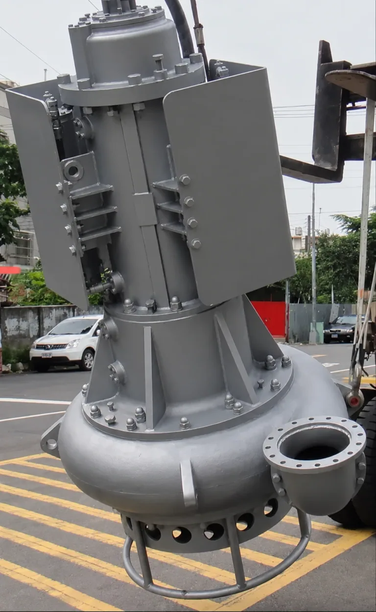
Submersible slurry pump
Motor, intake and flanged discharge.
Fleet and production
A working register of the principal units used in dredging, hydraulic fill and reclamation planning.
Equipment register
Submersible dredgers, hopper fleet, booster pumping, HDPE pipeline and support plant are coordinated around the project requirement.
| Group | Equipment | Available unit / role |
|---|---|---|
| Dredgers | 16″ submersible DP400 class dredger | 1 unit |
| Dredgers | 14″ submersible DP200 class dredger | 1 unit |
| Dredgers | 10″ 50HP submersible dredger | 1 unit |
| Dredgers | 8″ 75HP submersible dredger | 1 unit |
| Hopper fleet | Hopper dredgers | 10 units · 100 m³ each |
| Pumping & pipeline | Booster pump station | 1 unit · 350–450 kW |
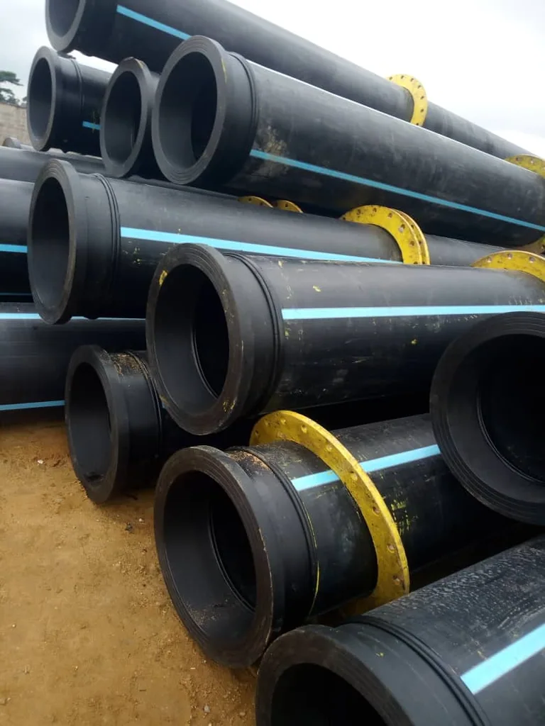
| Pumping & pipeline | HDPE pipeline | 2 km · 8–16″ |
| Support fleet | Marine & earthworks support | Tugboats, workboats, welding and anchor barges, 20–25 t excavators, D6–D8 bulldozers and vibro-compactors |
Hydraulic fill estimator
Planning basis: combined 160–350 m³/h (DP-200 + DP-50BL + DP-75). Final output requires a source and pipeline test run.
1,280–2,800 m³ per 8-hour shift; 140–400 m typical discharge distance. Longer reaches require project-specific hydraulic modelling.
Scroll horizontally to see all four columns.
| System | Discharge | Power / duty | Primary project role |
|---|---|---|---|
| TOYO DP-200-12A | 12 in | 160 kW | Primary heavy-duty sand / hydraulic fill production |
| TOYO DP-50BL | 10 in | Medium duty | Secondary production / fill / stockpile support |
| TOYO DP-75B | 8 in | Medium duty | Supplementary / confined dredging operations |
| Hydra-Tech HT006X8 | 8 in hydraulic | Hydraulic drive | Dewatering / dirty-water / support pumping; not primary abrasive sand dredging |
“Medium duty” is the profile’s duty description; numeric power is not specified for those two systems.
Supporting fleet
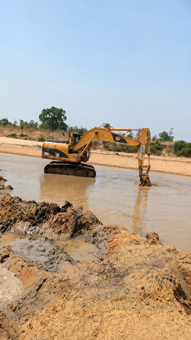
Tugboats, workboats, welding and anchor barges, 20–25 t excavators, D6–D8 bulldozers and vibro-compactors support the dredging and placement system.
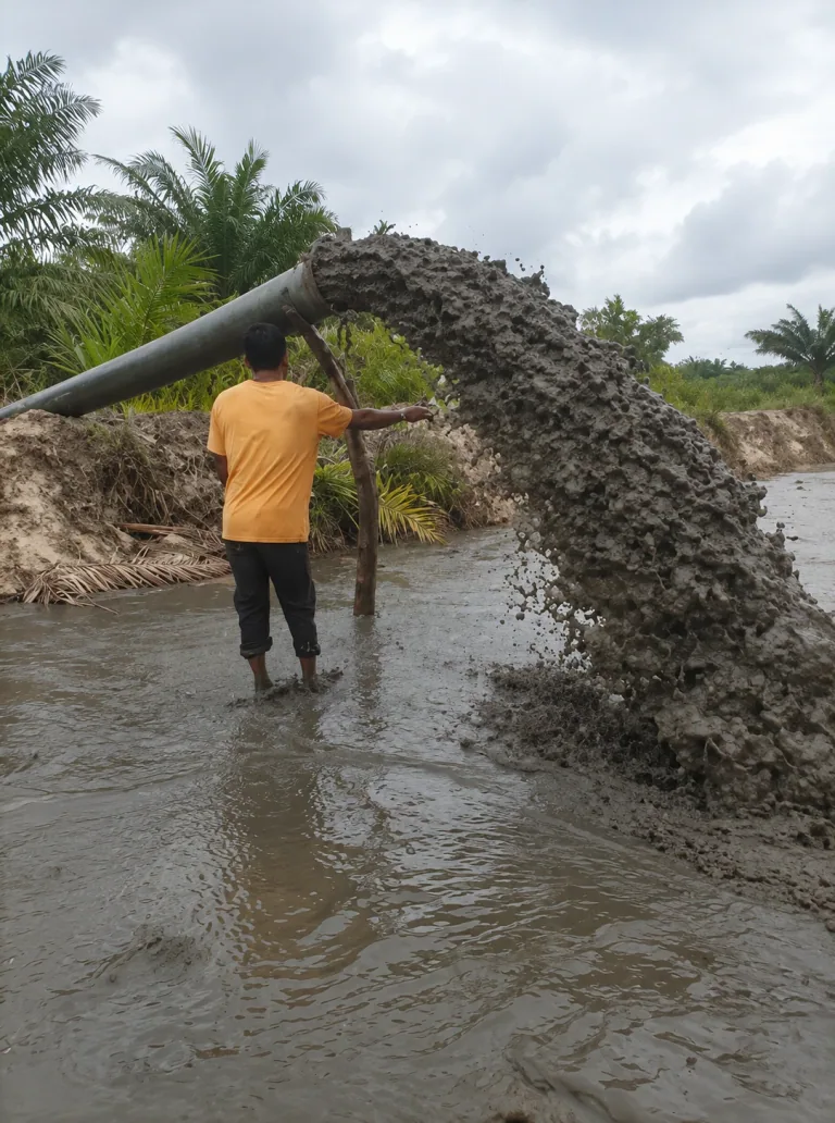
Hydraulic placement
Discharge arrangements follow the source material, pipeline route and placement area.
Equipment in view
Motor, intake and flanged discharge.
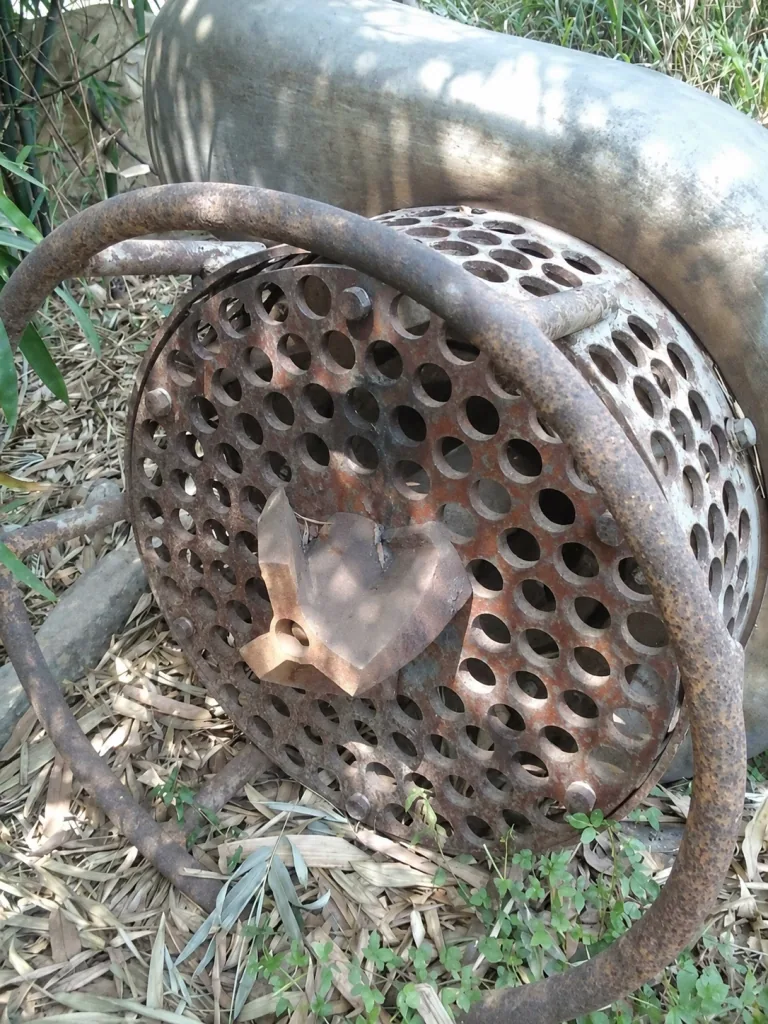
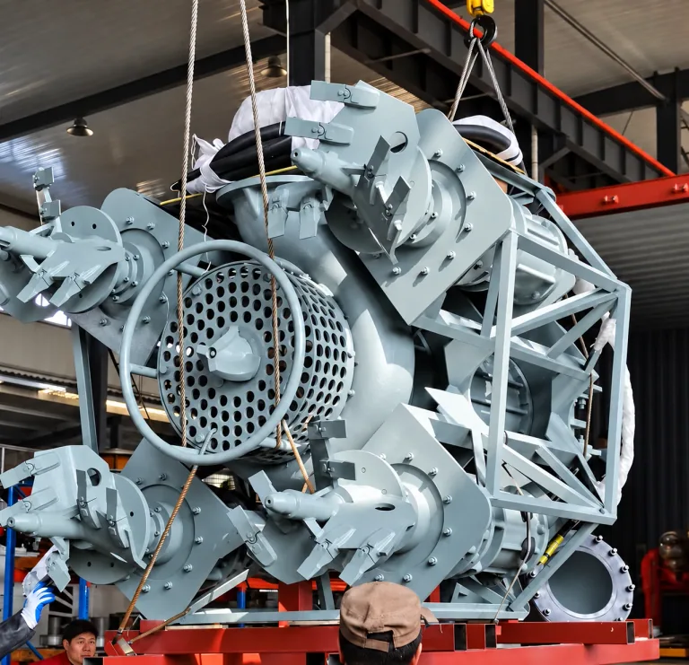
Screen and agitator at the pump intake.
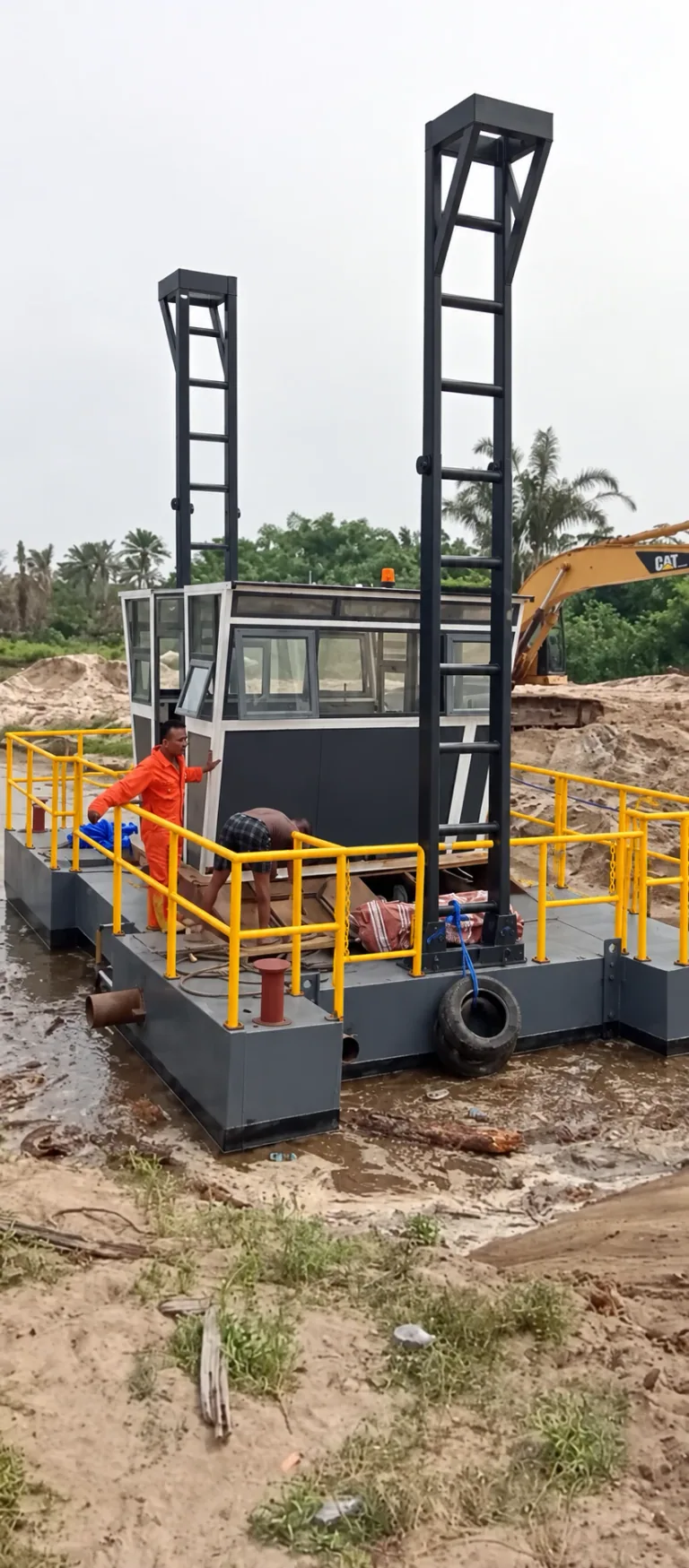
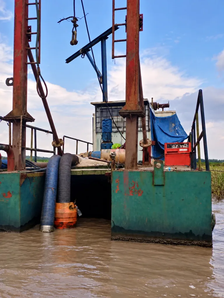
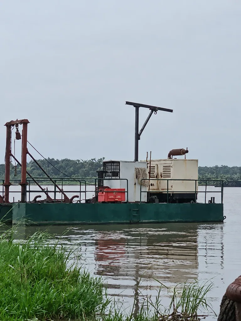
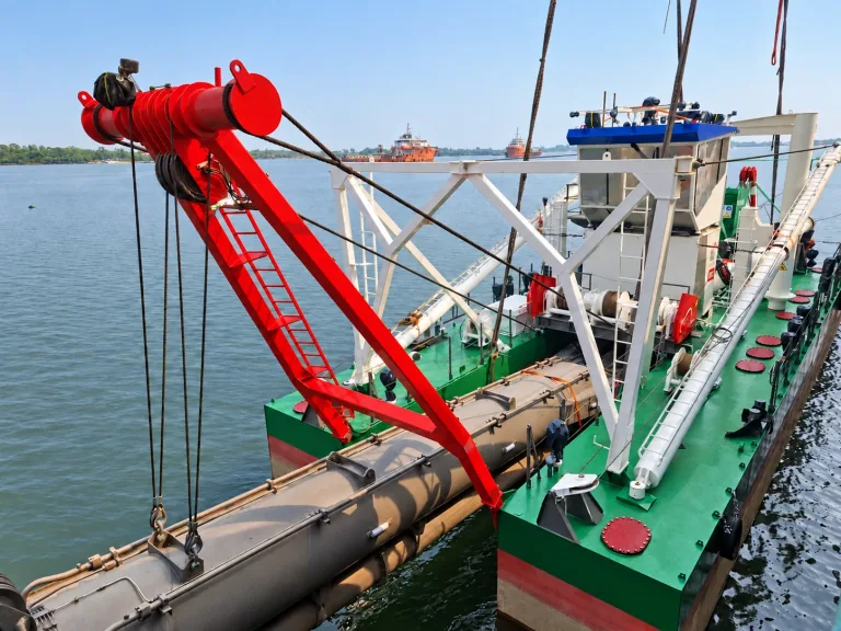
Cabin, upright frames and working deck.
Manufacturer references
Equipment-type examples, not identified Ruach-owned units or models in the register.
Perforated intakes and surrounding agitators.
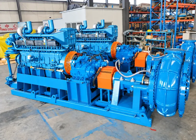
Engine, coupling and centrifugal pump on a skid.
Dredger deck
Deck-mounted pipework and handling gear.
Configuration notes
Profile planning figures require source verification and a project-specific test run.
Combined planning range only. Final output depends on source quality, dredging depth, distance, elevation and a pipeline test run.
Company profile: slides 12 and 14.
The profile recommends this configuration for HT006X8. It is not an installed-unit specification or independently verified OEM rating.
| Parameter | Profile recommendation |
|---|---|
| Engine | 150–180 HP mechanical diesel |
| Hydraulic pump | Variable-displacement axial-piston |
| Maximum hydraulic output | 70 GPM / 265 L/min |
| Working pressure | 170–190 bar / 2,500–2,800 psi |
| Reservoir | 350–400 L, AW46 hydraulic oil |
| Filtration | 10 micron return filtration |
| Cooling | Large hydraulic oil cooler |
| Hoses | 1.5 in pressure/return + case drain |
| Discharge | 8 in hose or HDPE line packages |
Non-flammable service only unless OEM confirmation and refinery HSE approval are obtained. Not a primary abrasive sand-slurry dredging pump.
Company profile: slides 18–19.